Search Engineering parts or work

1

This is the head of your page Example HTML page This is the body of your page.

Monday, March 15, 2010

Die operations and types
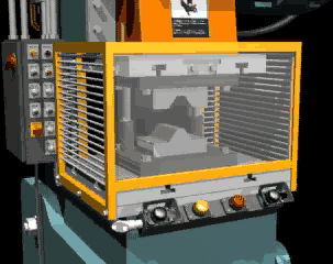


Die operations and types


Die operations are often named after the specific type of die that performs the operation. For example a bending operation is performed by a bending die. Operations are not limited to one specific die as some dies may incorporate multiple operation types:

Bending:

The bending operation is the act of bending blanks at a predetermined angle. An example would be an "L" bracket which is a straight piece of metal bent at a 90° angle. The main difference between a forming operation and a bending operation is the bending operation creates a straight line bend (such as a corner in a box) as where a form operation may create a curved bend (such as the bottom of a drinks can).


Blanking:

A blanking die produces a flat piece of material by cutting the desired shape in one operation. The finish part is referred to as a blank. Generally a blanking die may only cut the outside contour of a part, often used for parts with no internal features.Three benefits to die blanking are:


1. Accuracy. A properly sharpened die, with the correct amount of clearance between the punch and die, will produce a part that holds close dimensional tolerances in relationship to the parts edges.

2. Appearance. Since the part is blanked in one operation, the finish edges of the part produces a uniform appearance as opposed to varying degrees of burnishing from multiple operations.

3. Flatness. Due to the even compression of the blanking process, the end result is a flat part that may retain a specific level of flatness for additional manufacturing operations.

Broaching: The process of removing material through the use of multiple cutting teeth, with each tooth cutting behind the other. A broaching die is often used to remove material from parts that are too thick for shaving.

Bulging: A bulging die expands the closed end of tube through the use of two types of bulging dies. Similar to the way a chefs hat bulges out at the top from the cylindrical band around the chefs head.

1. Bulging fluid dies: Uses water or oil as a vehicle to expand the part.
2. Bulging rubber dies: Uses a rubber pad or block under pressure to move the wall of a workpiece.

Coining: is similar to forming with the main difference being that a coining die may form completely different features on either face of the blank, these features being transferred from the face of the punch or die respectively. The coining die and punch flow the metal by squeezing the blank within a confined area, instead of bending the blank. For example: an Olympic medal that was formed from a coining die may have a flat surface on the back and a raised feature on the front. If the medal was formed (or embossed), the surface on the back would be the reverse image of the front.

Compound operations: Compound dies perform multiple operations on the part. The compound operation is the act of implementing more than one operation during the press cycle.

Compound die: A type of die that has the die block (matrix) mounted on a punch plate with perforators in the upper die with the inner punch mounted in the lower die set. An inverted type of blanking die that punches upwards, leaving the part sitting on the lower punch (after being shed from the upper matrix on the press return stroke) instead of blanking the part through. A compound die allows the cutting of internal and external part features on a single press stroke.

Die forming


Die forming


Forming dies are typically made by tool and die makers and put into production after mounting into a press. The die is a metal block that is used for forming materials like sheet metal and plastic. For the vacuum forming of plastic sheet only a single form is used, typically to form transparent plastic containers (called blister packs) for merchandise. Vacuum forming is considered a simple molding thermoforming process but uses the same principles as die forming. For the forming of sheet metal, such as automobile body parts, two parts may be used, one, called the punch, performs the stretching, bending, and/or blanking operation, while another part, called the die block, securely clamps the workpiece and provides similar, stretching, bending, and/or blanking operation. The workpiece may pass through several stages using different tools or operations to obtain the final form. In the case of an automotive component there will usually be a shearing operation after the main forming is done and then additional crimping or rolling operations to ensure that all sharp edges are hidden and to add rigidity to the panel.
Die components

Die block
Punch plate
Blank punch
Pierce punch
Stripper plate
Pilot
Dowel Pin
Back gage
Finger stop

Die (manufacturing)

Die (manufacturing)

A die is a specialized tool used in manufacturing industries to cut or shape material using a press. Like molds and stencils, dies are generally customized to the item they are used to create. Products made with dies range from simple paper clips to complex pieces used in advanced technology.

Collet


Collet


A collet (pronounced ) is a holding device—specifically, a subtype of chuck—that forms a collar around the object to be held and exerts a strong clamping force on the object when it is tightened via a tapered outer collar. It may be used to hold a workpiece or a tool.

Nomenclature variations


Generally, a collet chuck, considered as a unit, consists of a tapered receiving sleeve (often integral with the machine spindle), the collet proper (usually made of spring steel), which is inserted into the receiving sleeve, and (often) a cap that screws over the collet, clamping it via another taper.
Usually in shop-floor terminology, the terms collet and chuck are used in contradistinction; users speak of holding a workpiece or tool with either a collet or a chuck. This usage refers to the same distinction as does speaking of using either a collet chuck or another type of chuck (scroll chuck, independent-jaw chuck, etc.); the two usages are different ways of saying the same thing. The difference lies in how one thinks of the overall chain of connection between the machine spindle and the thing being attached to it (workpiece or tool). In general terms, the overall system of holding constitutes a chuck, but practically, the receiving sleeve for a collet is often integral with the machine spindle, and from the point of view of naming the parts that are added on to the spindle, they are either a collet (± cap) or a chuck (such as a scroll chuck).[citation needed]

Magnetic


Magnetic

Used for holding ferromagnetic workpieces, a magnetic chuck consists of an accurately centered permanent magnet face. Electromagnets or permanent magnets are brought into contact with fixed ferrous plates, or pole pieces, contained within a housing. These pole pieces are usually flush with the housing surface. The part (workpiece) to be held forms the closing of the magnetic loop or path, onto those fixed plates, providing a secure anchor for the workpiece.

Electrostatic


Electrostatic

Commonly used for holding silicon wafers during lithography processes, an electrostatic chuck comprises a metal base-plate and a thin dielectric layer; the metal base-plate is maintained at a high-voltage relative to the wafer, and so an electrostatic force clamps the wafer to it. Electrostatic chucks may have pins, or mesas, the height of which is included in the reported dielectric thickness; a design by Sandia National Laboratory uses a patterned silicon-dioxide dielectric to form the pins.[6]

Vacuum chuck


Vacuum chuck

A vacuum chuck is primarily used on non-ferrous materials, such as copper, bronze, aluminum, titanium, plastics, and stone. In a vacuum chuck, air is pumped from a cavity behind the workpiece, and atmospheric pressure provides the holding force. Vacuum produces a hold down force of 14.7 psi (101 kPa) at sea level, decreasing at higher elevations where the atmospheric pressure is lower. The use of vacuum chucks is increasing.

Special Direct System (SDS)


Special Direct System (SDS)


Developed by Bosch in 1975 for hammer drills, the SDS uses a cylindrical shank on the tool, with indentations to be held by the chuck.[1] A tool is inserted into the chuck by pressing in, and is locked in place until a separate lock release is used. The rotary force is supplied through wedges that fit into two or three open grooves. The hammer action actually moves the bit up and down within the chuck since the bit is free to move a short distance. Two sprung balls fit into closed grooves, allowing movement whilst retaining the bit. SDS relies on a tool having the same shank diameter as the chuck; there are three standard sizes:


SDS-Plus:

a 10 mm shank with two open grooves held by the driving wedges and two closed grooves held by locking balls. This is the most common size and takes a hammer up to 4 kg. The wedges grip an area of 75 mm² (0.116 sq in) and the shank is inserted 40 mm into the chuck.[2]


SDS-top:

a 14 mm shank similar to SDS-plus, designed for hammers from 2 to 5 kg. The grip area is increased to 212 mm² (0.329 sq in) and the shank is inserted 70 mm. This size is uncommon.[3]


SDS-max:

an 18 mm shank with three open grooves and locking segments rather than balls. It is designed for hammers over 5 kg. The wedges grip an area of 389 mm² (0.603 sq in) and the shank is inserted 90 mm.[4]


Many SDS drills have a "rotation off" setting, which allows the drill to be used for chiselling. The name SDS comes from the German steck, dreh, sitzt (insert, twist, fits). German-speaking countries may use Spannen durch System (Clamping System), though Bosch uses Special Direct System for international purposes.[5]

Multi-jaw


Multi-jaw


For special purposes, and also the holding of fragile materials, chucks are available with six or eight jaws. These are usually of the self-centering design, and may be built to very high standards of accuracy.
Two-jaw chucks are available and can be used with soft jaws (typically an aluminium alloy) that can be machined to conform to a particular workpiece.
Many chucks have removable jaws (often the top part is removable leaving the base or 'master jaw' assembled with the scroll), which allows the user to replace them with new jaws, specialized jaws, or soft jaws.


An older and larger 4 jaw chuck. Note how it is able to grip an irregularly cut piece of used metal. Though not found on small chucks it is common for larger chucks (the one in the second photo was made around 1900 and is 24" in diameter) to have many of the features of a Lathe faceplate. The jaws are stepped on one side and full height for gripping on the other and are reversible. Generally the jaws are usable for holding either outside as shown here, or inside as in gripping the inside of a pipe.

Independent-jaw


Independent-jaw


On an independent-jaw chuck, each jaw can be moved independently. Because they most often have four jaws, the term four-jaw chuck without other qualification is understood by machinists to mean a chuck with four independent jaws. The independence of the jaws makes these chucks ideal for (a) gripping non-circular cross sections and (b) gripping circular cross sections with extreme precision (when the last few hundredths of a millimeter [or thousandths of an inch] of runout must be manually eliminated). The non-self-centering action of the independent jaws makes centering highly controllable (for an experienced user), but at the expense of speed and ease. Four-jaw chucks are almost never used for tool holding. Four-jaw chucks can be found on lathes and indexing heads.
Self-centering chucks with four jaws also can be obtained. Although these are often said to suffer from two disadvantages: inability to hold hex stock, and poor gripping on stock which is oval, only the latter is true. Even with three jaw self centering chucks, work which is not of uniform section along the work (and which is not free of spiral or 'wind')should not be gripped, as the jaws can be strained and the accuracy permanently impaired.
Four-jaw chucks can easily hold a workpiece eccentrically if eccentric features need to be machined.

Drill chuck


Drill chuck


A drill chuck is a specialised self-centering, three-jaw chuck, usually with capacity of less than 0.5 in (13 mm) and rarely greater than 1 in (25 mm), used to hold drill bits or other rotary tools. This is the type of chuck that a machining layperson is most likely to be familiar with.
Some high precision chucks use ball thrust bearings to reduce friction in the closing mechanism and maximizing drilling torque. One brand name for this type of chuck, which is often used generically, is Super Chuck.[citation needed]
A pin chuck is a specialized chuck designed to hold small drills (less than 1 mm (0.039 in) in diameter) that could not be held securely in a normal drill chuck. The drill is inserted into the pin chuck and tightened, the pin chuck is then inserted into the larger drill chuck so that the operation can continue. Pin chucks are also found on high speed rotary tools, such as die grinders and jig grinders.

Chuck (engineering)


Self-centering


A self-centering chuck uses dogs (usually called jaws), interconnected via a scroll gear (scroll plate), to hold onto a tool or workpiece. Because they most often have three jaws, the term three-jaw chuck without other qualification is understood by machinists to mean a self-centering three-jaw chuck. The term universal chuck also refers to this type. These chucks are best suited to grip circular or hexagonal cross-sections when very fast, reasonably accurate (±0.005 in TIR) centering is desired.
Sometimes this type of chuck has four or six jaws instead of three. More jaws confer more secure grip (if the work is truly cylindrical) and thin-walled work will deform less. Four jaws are also useful for square bar work.
Independent-jaw (non-self-centering) chucks with three jaws also can be obtained.
There are hybrid self-centering chucks that have adjustment screws that can be used to further improve the concentricity after the workpiece has been gripped by the scroll jaws. This feature is meant to combine the speed and ease of the scroll plate's self-centering with the runout-eliminating controllability of an independent-jaw chuck.
Three-jaw chucks can often be found on lathes and indexing heads.


Chuck (engineering)


Self-centering

A self-centering chuck uses dogs (usually called jaws), interconnected via a scroll gear (scroll plate), to hold onto a tool or workpiece. Because they most often have three jaws, the term three-jaw chuck without other qualification is understood by machinists to mean a self-centering three-jaw chuck. The term universal chuck also refers to this type. These chucks are best suited to grip circular or hexagonal cross-sections when very fast, reasonably accurate (±0.005 in TIR) centering is desired.
Sometimes this type of chuck has four or six jaws instead of three. More jaws confer more secure grip (if the work is truly cylindrical) and thin-walled work will deform less. Four jaws are also useful for square bar work.
Independent-jaw (non-self-centering) chucks with three jaws also can be obtained.
There are hybrid self-centering chucks that have adjustment screws that can be used to further improve the concentricity after the workpiece has been gripped by the scroll jaws. This feature is meant to combine the speed and ease of the scroll plate's self-centering with the runout-eliminating controllability of an independent-jaw chuck.
Three-jaw chucks can often be found on lathes and indexing heads.

Bystronic


Bystronic

Bystronic is an internationally active Swiss manufacturer of machine tools for the processing of sheet metal and other sheet materials. Its headquarters are in Niederönz. The company produces laser- and water jet cutting systems as well as press brakes. In addition to the manufacturing facility in Niederönz (Bystronic Laser AG), Bystronic has further manufacturing plants in Gotha (Deutschland) and Tianjin (China). Since 1994, Bystronic has been part of the Zurich industrial holding Conzzeta.

Backgauge


Backgauge

A backgauge is a mechanical system, normally attached to a brake press. Its main function is to interface with the brake press computer numerical control (CNC), moving along several different axes in order to position a piece of metal for forming.
Backgauges typically have anywhere from 1 to 7 axes of movement. Each of these individual axis is controlled by a separate electric motor. Often a brake press is sold to a customer in conjunction with a backgauge.
On an extrusion saw, a backgauge is responsible for feeding material at exact amounts past a saw blade. It is responsible for the accuracy of the piece's cut length.

This metalworking article is a stub. You can help Wikipedia by expanding it.
vde

Angle plate

Angle plate

An angle plate is a work holding device used as a fixture in metalworking.
The angle plate is made from high quality material (generally spheroidal cast iron) that has been stabilized to prevent further movement or distortion. Slotted holes or T bolt slots are machined into the surfaces to enable the secure attachment or clamping of workpieces to the plate, and also of the plate to the worktable.
Angle plates also may be used to hold the workpiece square to the table during marking out operations.
Adjustable angle plates are also available for workpieces that need to be inclined, usually towards a milling cutter.